Ez 20brake Controller Wiring Diagram

Universal Installation Kit For Trailer Brake Controller 7 Way Rv

Tekonsha Voyager Trailer Brake Controller 1 To 4 Axles
Troubleshooting Brake Controller Installations Etrailer Com
How To Install A Electric Trailer Brake Controller On A Tow Vehicle

Diagram Of A Brake Controller Intallation With Images Tekonsha

Unique Electric Brake Controller Wiring Diagram Australia With
Important facts to remember 1.
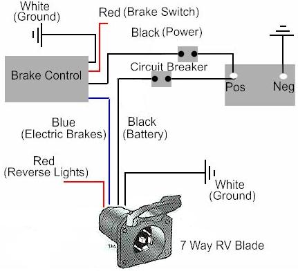
Ez 20brake controller wiring diagram. Route this wire to a 20 amp or 30 amp breaker under the hood and then to the positive post on the battery. A wiring diagram is a streamlined standard photographic depiction of an electric circuit. Read and follow all instructions carefully before wiring brake control. Splice the brake control brake control s red wire to light green wire using a wire tap.
Otherwise the arrangement won t work as it should be. There are now two wires connected to the positive post. Each part should be placed and linked to different parts in specific way. Wiring instructions for electronic brake controls p n 4399 rev k generic wiring diagram read this first.
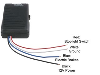
Ezgo wiring diagram you ll need an extensive skilled and easy to understand wiring diagram. Not merely will it help you accomplish your required results more quickly but also make the whole process simpler for everyone. The black wire coming out of the brake controller is the brake controller power supply. The brake control must be installed with a 12 volt negative ground.
Has two rows of wires. The 12 volt hot lead and the brake controller power supply. It reveals the elements of the circuit as streamlined shapes as well as the power and signal links in between the gadgets. Ezgo txt wiring diagram 1997 ezgo txt wiring diagram 2001 ezgo txt wiring diagram 2005 ezgo txt wiring diagram every electric structure is made up of various unique pieces.
Keep these instructions with the brake control for future reference. With this sort of an illustrative guide you ll be capable of troubleshoot avoid and total your tasks easily.
Electric Trailer Brake Controller Installation Page 3 Nissan

Installing An Electric Brake Controller On 2007 2013 Gm Full Size

Brake Controller Wiring Diagram Tekonsha Diagram

Electric Motorcycle Howto Wiring Electric Bike Wiring Diagram
Redarc Tow Pro Elite Install 2019 Ford Ranger And Raptor Forum

Tekonsha Trailer Brake Control Proportional

Top 20 Designer Shower Curtains With Valance Trailer Wiring
Trailer Connector Pigtail Replacement General Trailer Wiring Guide

Trailer Brake Controller Install Gm Chevy Gmc Express Van Savana

Wiring Diagram For Trailer Light 4 Way With Images Trailer

Brake Control Future Reference Generic Wiring Diagram Boat
Electric Brake Controller Installation On Dodge Ram Trucks To 2012

Mercruiser Trim Solenoid Wiring Diagram Yahoo Image Search
