Ez Tcu Controller Wiring Diagram
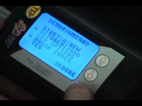
Ez Tcu Transmission Controller Setup And Advanced Settings

Anyone Familiar With Tci Handheld Controllers For Auto Archive
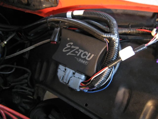
Installing Tci S Ez Tcu Late Model Gm Transmission Controller

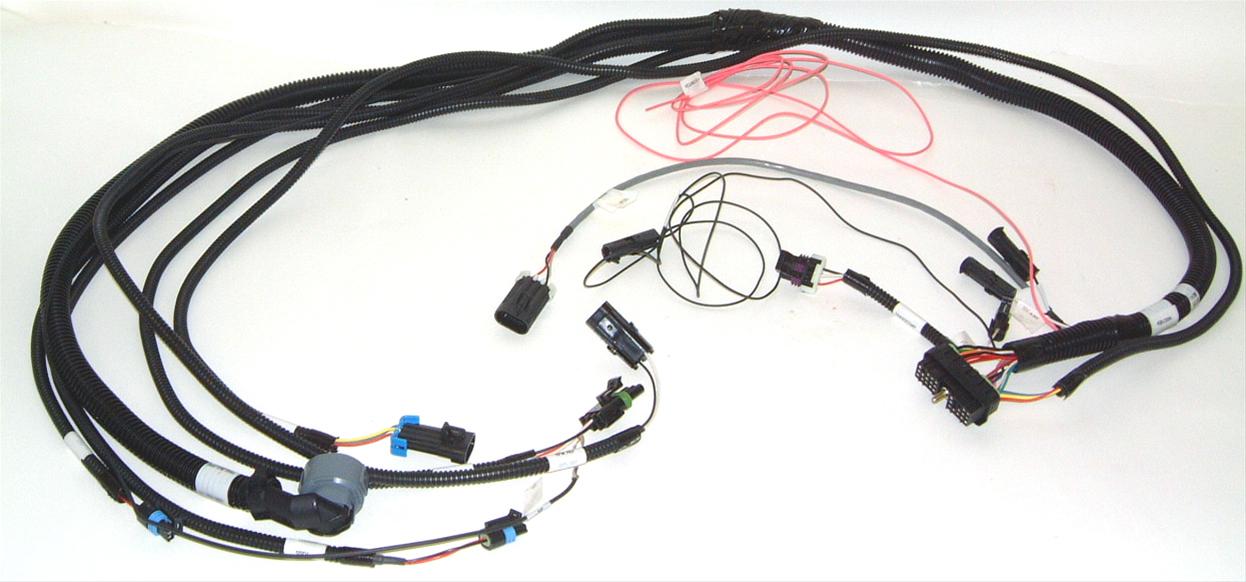
Tci Ez Tcu Transmission Controller Harness Options Youtube

Ez Wiring 3 Wiring Diagram
Tci Auto 377000

Tci s tcu computer software and wiring.
Ez tcu controller wiring diagram. If using a clean processed tach signal the tach in rpm module wire in the ez tcu wiring harness is connected directly to that source the tach output from an ignition box etc. Will vance covers the basics of installing the tci ez tcu controller and wiring harness. Module wire in the ez tcu wiring harness directly to that terminal. The ez tcu allows for maximum electronic control over shift points shift firmness and shift speed.
The tcu will be damaged. In a case like that the rpm module is required since what you are really doing is connecting to the negative side of a dwell controlled coil. This tci transmission control unit tcu system is designed to be used with the following transmissions. When you receive your ez tcu it will come with much more detailed instructions.
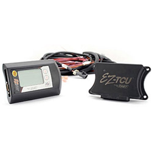
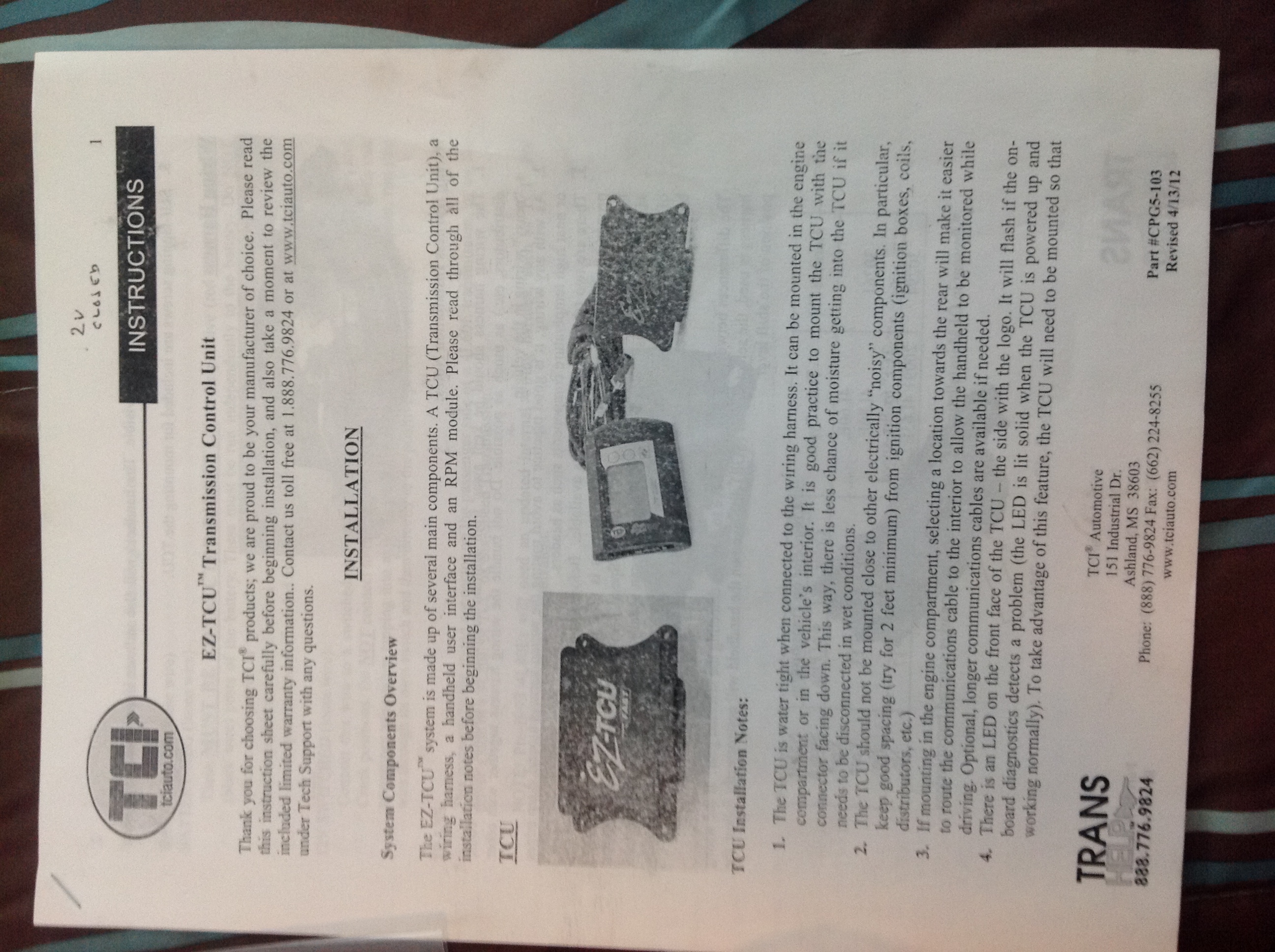
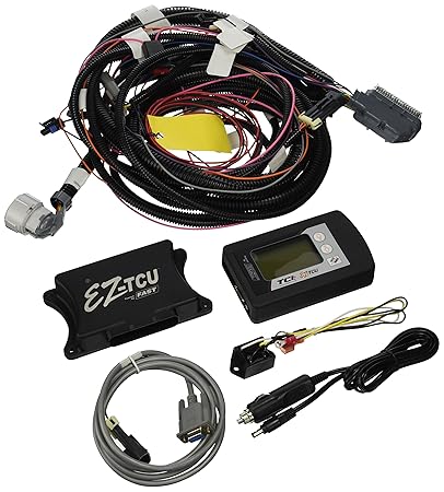
The ez tcu system is made up of several main components. Do not bypass the rpm module and connect the tach in rpm module wire in the ez. Do not connect anything from the ez tcu system to the coil rpm module or. These transmissions are fully electronic and will not shift automatically with out a transmission control system connected to it.
Self diagnostics allow users of every skill level to fully utilize the ez tcu. A tcu transmission control unit a a tcu transmission control unit a wiring harness a handheld user interface and an rpm module. Ford aode 4r70w ford e4od 4r100 gm 4l60e 4l65e and gm 4l80e. Will vance goes over the wiring options for the tci ez tcu transmission controller.
Tci Ez Tcu Installation Youtube
Tcu Tps Signal With Dbw Ls1tech Camaro And Firebird Forum

Nh 8322 Eztcutm Transmission Control Unit Gm 4l60 4l65 4l70 4l80
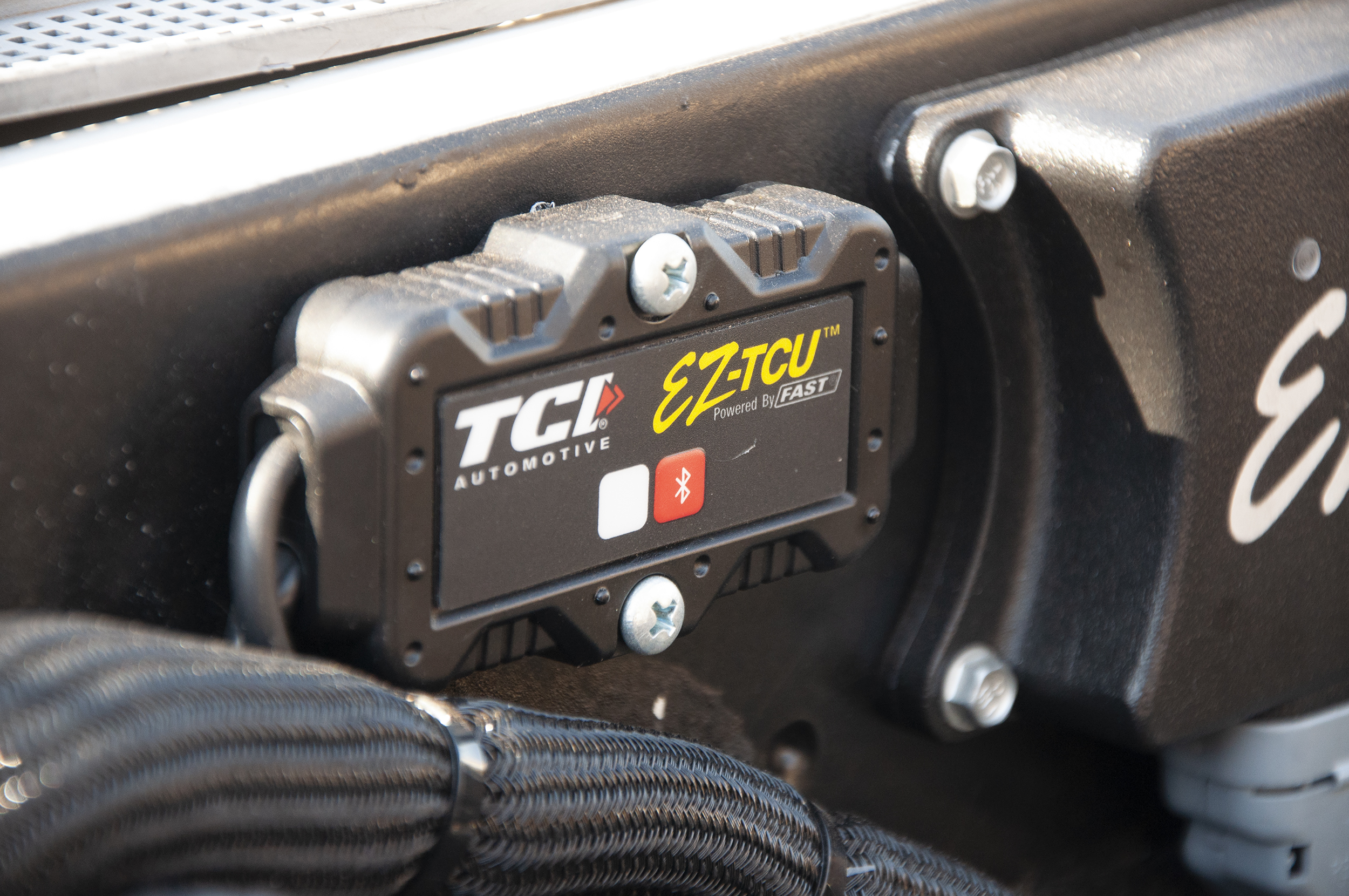
Total Control Tci S New Wireless Bluetooth Transmission Controller

Got The Actual Gear Indicator And Tcc Lockup Working Now

Fast Ez Tcu 4l60e Tps Error Code Fix Youtube

Tci 30294 Ez Tcu Wiring Harness 2009 Up Gm 4l70e Transmissions Jegs

Ez Tcu Transmission Contoller On A Sbc Nissan Pick Up Part6
Tci 302820 Ez Tcu Transmission Control Unit Amazon In Car

Sema 2018 Tci S Ez Tcu 2 0 Incorporates Bluetooth To Control

Tci Ez Tcu And Upgrades For Biting The Bullitt S Streetfighter

Spotter S Guide 4l60e Transmission Chevy Tahoe Transmission

He 4028 Transmission External Wiring Harness On 4l65e