System Sensor D4120 Wiring Diagram
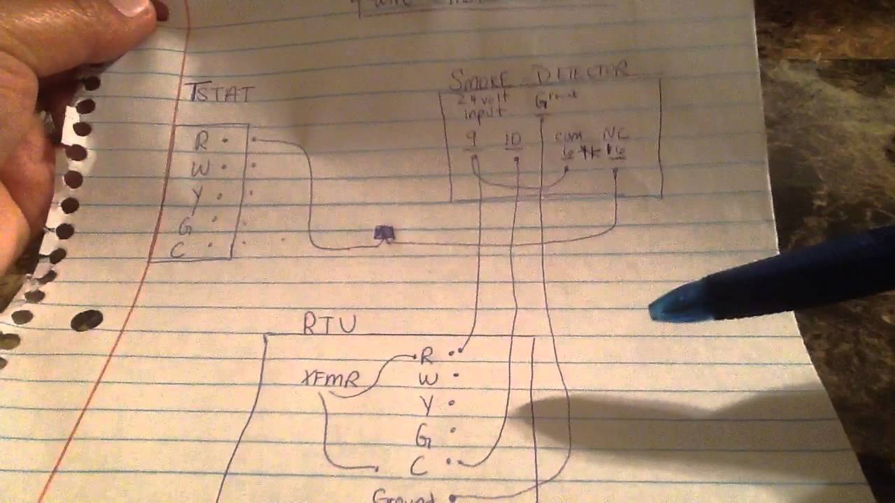
Wiring A Hvac Ducted Smoke Detector Easy Way Youtube

System Sensor Wiring Diagram Wiring Diagram

Conventional Duct Smoke Detectors Hvac Smoke Detectors System

Ld4p120x Duct Detector Wiring Diagram Wiring Diagram
Totaline P270 3000pl Wiring Diagram Wiring Diagram
Https Www Systemsensor Com En Us Documents Dh100acdclp Manual I56 0084 Pdf

The d4120 and d4p120 can be reset by a momentary power interrup tion the reset button on the front cover the control panel or remote reset accessory.
System sensor d4120 wiring diagram. Also note that the system sensor d4120 is the replacement for the dh100acdclp the reason to mentioned this is the fact that system sensor was smart when creating the newer d4120 by carrying over the same terminal numbers. D4120 products system sensor system sensor. The feature is only available on the d4120 4 wire conventional models. Read system sensor s applications guide for duct smoke detectors hvag53 which provides information on detector spacing placement zoning wiring and special applications.
4 wire magnet test location sold seperately 3 general description smoke introduced into an air duct system will be distributed throughout the entire building. Features 4 wire photoelectric integrated low flow technology air velocity rating from 100 ft min to 4 000 ft min 0 5 m s to 20 32 m sec. Wiring for 4 wire duct smoke detector and accessories important notes on 2 1 sensor to power capability 2 1 sensor to power capability is not available for all innovairflex models. Visible and audible system annunciation.
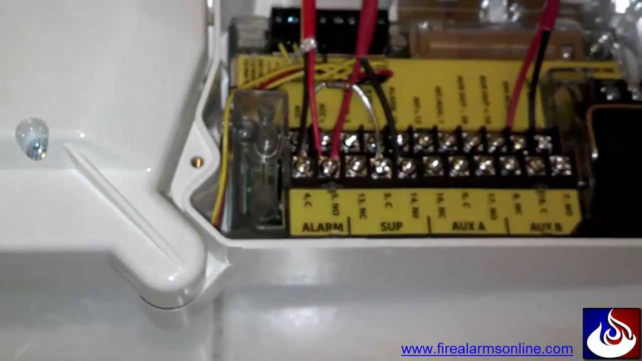
System sensor is a global manufacturer of fire and life safety devices in smoke detection carbon monoxide detection and notification technology. For reference we are going to be covering the connections on the system sensor d4120 model duct detector as this is the most common version used by mechanical contractors. Nfpa standards 72 and 90a should also be refer enced for detailed information. An initial appearance at a circuit representation could be confusing however if you could read a metro map you could read schematics.
Ordering information part no. Description d4120w watertight 4 wire photoelectric low flow duct smoke detector accessories 2d51 4 wire conventional photoelectric sensor head m02 04 00 test magnet. As with our duct smoke detectors all duct smoke detector accessories are ul listed. System sensor smoke detector wiring diagram a novice s guide to circuit diagrams.
Wiring diagram for d4120 to ssk451 with ps24lo if you have any questions regarding system sensor products codes or their application please call technical support at 1 800 sensor2 736 7672 ext. The d4120 and d4p120 leds indicate the status of power maintenance trouble and local alarm conditions. The d4120 and d4p120 incorporate a cover tamper feature.

Apollo Smoke Detector Wiring Diagram

E Bike Controller Wiring Diagram 2 With Images Electric Bike

Wiring Diagram For Chinese 110 Atv The Wiring Diagram Atv Pit

74c64 Edwards Smoke Detector Wiring Diagram Wiring Library

Smoke Detector Placement For Magnetic Door Holders Fire Alarms

20 Good Haynes Wiring Diagram Legend Ideas With Images Peugeot

Vw Golf Mk5 Gti Wiring Diagram Best Of Saleexpert Sharkawifarm Com

10 98 Lincoln Town Car Wiring Diagram Car Diagram In 2020 With

Fire Pump Wiring Diagram With Images Diagram Fire Protection

Alternator Wiring Diagram Toyota Corolla Electricidad Instalacion

7 3 Powerstroke Wiring Diagram Google Search With Images

Es200 Wiring Diagram Connection Scheme Automatic Sliding Doors

12 Nissan Murano Engine Wiring Diagram Engine Diagram In 2020
