T103 Wiring Diagram

How To Wire T103 Timer
Intermatic T103 Wiring Youtube

Solved I Want To Hook Up A New Intermatic T103 Timer I Have 3

Pool Timer Wiring Help Please Doityourself Com Community Forums

Kv 4493 Time Clock Switch Wiring Diagram Wiring Diagram

How To Wire Intermatic T104 And T103 And T101 Timers
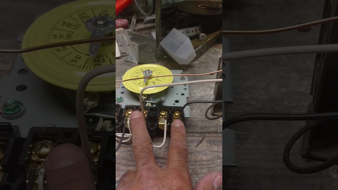
My question is in which locations 1 thru 4 do i wire the black and.
T103 wiring diagram. Intermatic t103 wiring diagram. I purchased an intermatic t timer switch and am unable to get the clock running. It shows the elements of the circuit as streamlined shapes as well as the power as well as signal links between the devices. Typical wiring diagram clock motor 120 240 volt 3 wire supply to loads ground line 2 line 1 a 2 4 gr.
Remove 1 2 inch of insulation from wire ends. Intermatic t103 wiring diagram what is a wiring diagram. T103 timer wiring diagram wiring diagram is a simplified okay pictorial representation of an electrical circuit. Use solid or stranded copper conductors only.
A wiring diagram is a streamlined traditional pictorial representation of an electric circuit. Assortment of intermatic t103 wiring diagram. Currently there are two white wires from a 1 leading to the timer itself. May use two wires of the same size and type.
Easy tips walk thru duration. Clean pool spa ultimate swimming pool care guide 145 669 views. A wiring diagram is a straightforward visual representation with the physical connections and physical layout of your electrical system or circuit. Wiring for model t103 intermatic timer.

How To Wire Intermatic T104 And T103 And T101 Timers

Universal Lawn Mower Ignition Switch Diagram Lawn Mower Lawn

Pin On Architecture

Cub Cadet Starting Problems Diagram Cub Cadet Cubs Outdoor

Cub Cadet Starting Problems Diagram Cub Cadet Cubs Outdoor

Dear Sgt Al How Do I Become A Police Officer With Images

Cub Cadet Starting Problems Diagram Cub Cadet Cubs Outdoor

Thomas T103 T 133 Skid Steer Loader Skid Steer Loader Heavy

Cub Cadet Starting Problems Diagram Cub Cadet Cubs Outdoor

Cub Cadet Starting Problems Diagram Cub Cadet Cubs Outdoor

Cub Cadet Starting Problems Diagram Cub Cadet Cubs Outdoor

Cub Cadet Starting Problems Diagram Cub Cadet Cubs Outdoor

Cub Cadet Starting Problems Diagram Cub Cadet Cubs Outdoor
