T104p3 Wiring Diagram

How To Wire Intermatic T104 And T103 And T101 Timers
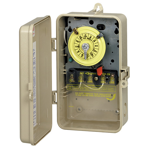
Intermatic T104p3 Pool Spa Mechanical Switch Beige 1000bulbs Com

How To Replace An Intermatic T104m 240v 208 277 V Pool Timer

Nk 9889 Basic 12v Relay Wiring Free Diagram

Gc 7377 99 Polaris Ranger 6x6 Wiring Diagrams Download Diagram

How To Wire A Finished Garage Home Electrical Wiring Finished
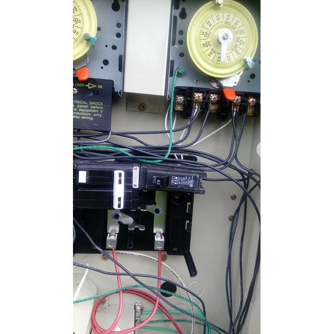
To make power connections remove 1 2 inch of insulation from wire ends.
T104p3 wiring diagram. Intermatic t104 supplementary manual. Intermatic t104p3 wiring diagram 22 11 2018 22 11 2018 5 comments on intermatic t104p3 wiring diagram these heavy duty mechanical time switches are designed for commercial industrial and residential applications and have the highest motor load ratings in the. An 115v pump will use twice the amperage as a 230v pump. Use solid or stranded copper only wire with insulation to suit.
Clean pool spa ultimate swimming pool care guide 145 669 views. Wiring for model t103 intermatic timer. 1 2 and 3 4 combination. How to replace an intermatic t104m 240v 208 277 v pool timer duration.
To make power connections remove 1 2 inch of insulation. Installation and or wiring must be in accordance with national and local electrical code requirements. P stands for plastic enclosure. Intermatic timer t104 wiring diagram download.
Assortment of intermatic timer t104 wiring diagram. Use 3 16 or larger screwdriver to tighten terminal. Easy tips walk thru duration. Wire gauge the selection of wire gauge between the timer and pump depends on three factors.
Insert bare ends of wire under the pressure plate. Each timer has different wiring options. Use solid or stranded copper only wire with insulation to suit installation. When you open the enclosure door there is translucent or solid black insulator covering the wiring.
Insert bare ends of wire under the pressure plate of terminals. The r stands for raintight. These mechanical timers last many years. Global english español deutsch.
See gauge selection table for normal service applica tions. To wire switch follow diagram above. Wiring instructions to wire switch follow diagram above. Hp supply voltage and distance.
It reveals the components of the circuit as streamlined forms and also the power and also signal links between the gadgets. If the distance to your pump is less than 50 feet for a 1hp or less pump on 230v you would need 14 gauge wire for 115v you would need 12 gauge wire. As long as insulator is in place it is safe to touch visible timer. Wiring diagram 240 v 2 wire and ground lr3730 154 02030 ul hologram label warning risk of fire or electric shock disconnect power at the circuit breaker s or disconnect switch es before installing or servicing.
Knockout dimensions bottom 2 1 2 and 3 4 knockout dimensions back side.

240v Single Phase Motor Wiring Diagram Wiring Diagram And

Mb 4819 Outlet Light Switch Wiring Diagrams Wiring Harness Wiring
Intermatic Timer Mechanism Only 220v T104m Inyopools Com

12 Complex Electric Motor Wiring Diagram Ideas With Images

Wiring Diagram For 220 Volt Generator Plug Outlet Wiring

Intermatic Pool Timers

Simple To Read Wiring Diagram For A Boat Boat Wiring Electrical

Ac Plug Wiring Diagram Con Imagenes Tecnologia Futurista

Marine Dual Battery Switch Wiring Diagram With Images Boat

Xm 5691 Jaguar Navigation Wiring Diagram Free Diagram

12 Citroen C3 Electrical Wiring Diagram Wiring Diagram In 2020

Rd 9228 280z Wiring Diagram Together With 280z Ignition Wiring

New Wiring Diagram For Kipor Generator Diagram Diagramsample
