T4 1 Block Diagram
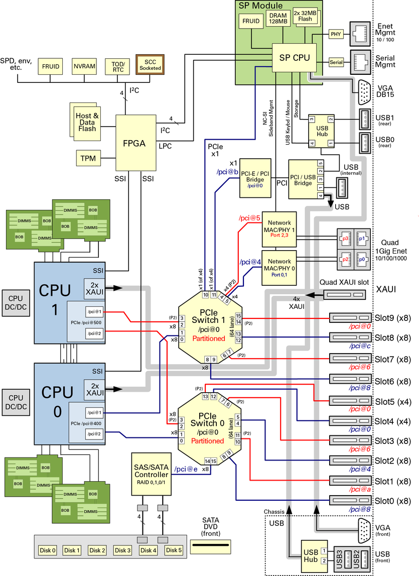
System Schematic Sparc T4 2 Server Html Document Collection
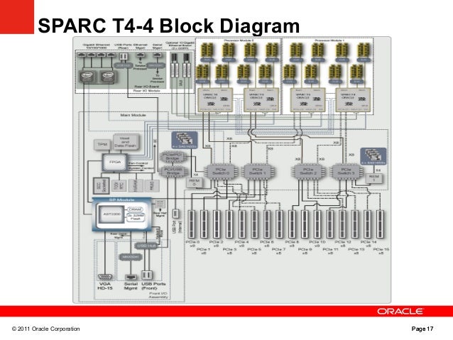
Sparc T4 4 System Technical Overview

Camper Wiring Diagram Diagrams Schematics And Motorhome With

Block Diagram Of Engine Management System Block Diagram Of Engine

Pdf Schematic Diagrams B 2 System Block Diagram B Schematic
Sap 1

The gpios are grouped into banks.
T4 1 block diagram. The following sections describe the t4 interface blocks. It is also having one summing point. Instrument cluster for t440 t470 used with epa2010 emission compliant engines. Each bank has its own vccio that sets the.
Signals and block diagrams are shown from the perspective of the interface not the core. Volkswagen vehicles diagrams schematics and service manuals download for free. Document includes block diagram block diagram 1. Incomplete vehicle certification document.
Aerodynamic mirror oat sensor location. General purpose i o logic and buffer the gpio support the 3 3 v lvttl and 1 8 v 2 5 v and 3 3 v lvcmos i o standards. If you continue browsing the site you agree to the use of cookies on this website. Download manual guide of vw t4 wiring diagram pdf in pdf that we indexed in manual guide.
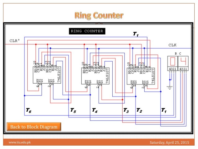
Radio control system block diagram details for fcc id spnt4 2400m made by zhuhai xingyu model products co ltd. The basic elements of a block diagram are a block the summing point and the take off point. Let us consider the block diagram of a closed loop control system as shown in the following figure to identify these elements. See mg 1 2 21 mg 1 2 24 direction of rotation.
T4 lamp block diagram details for fcc id p2rt4lamp made by kwo light co ltd. Locations of certification labels. The above block diagram consists of two blocks having transfer functions g s and h s. Figures 12 09 vi figure 2 1.
West coast mirror oat sensor. The t4 vertebra is the fourth thoracic vertebra that makes up the middle segment of spinal column of the human body. Document includes block diagram block diagram. The thoracic spinal vertebrae consist of 12 total vertebrae and are located.
2 11 in which vector 1 is 120 degrees in advance of vector 2 and the phase sequence is 1 2 3. In all wiring diagrams the same component designation code is used for a t45 38 t45 15.

Solved 2 10 Pts A 2 Pts Draw The Block Diagram For

Pin Diagram Of 8086 Microprocessor Geeksforgeeks

Block Diagram Interior Design Google Search Schematic Design

Arduino Based Smart Home Automation Block Diagram With Images

Block Diagram Of The Proposed System Architecture For
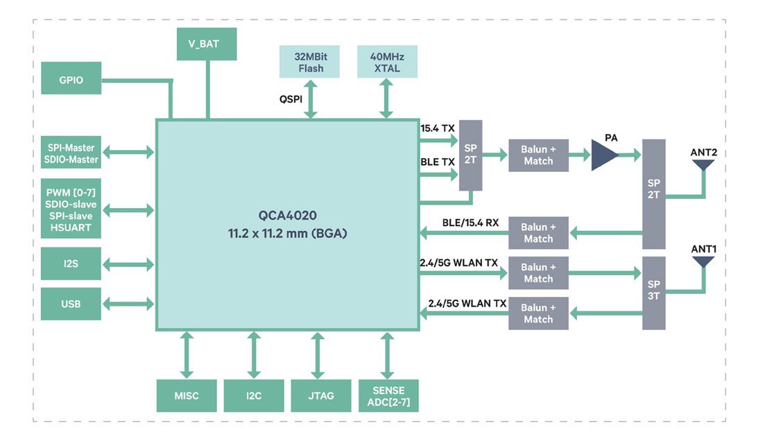
T4g Q4020 For Google Iot Cloud Service Tantiv4

New Wiring Scheme Diagram Wiringdiagram Diagramming Diagramm

Micro Programmed Versus Hardwired Control Units
Lenovo Thinksystem St50 Server E 2100 Product Guide Lenovo Press

Big 3 Upgrade Diagram Luxury Collection Big 3 Wire Upgrade Diagram

Pdf Design And Implementation Of Igbt Based Constant Voltage

Block Diagram Representation Of Battery Charger Download

Fuse Block Ground Block Wiring Fuses Car Fuses Motorcycle Wiring
