T8 Ballast Wiring Diagram Robertson

Robertson 5p20135 Model Iea432t8120n B Oem Pak Of 10 Fluorescent

Robertson 1p20132 Oem Pak Of 20 Fluorescent Eballasts For 2 F40t12
Wmtlubz46g5yxm

10 Pack Sylvania 49865 Qhe 3x32t8 Unv Isl Sc T8 Fluorescent

Advance Imh 150h Bls M Ehid 150w Mh Ballast Stud Mount

Qhe 2x32t8 Unv Dali Sylvania 51355 Fluorescent T8 Ballast

50 videos play all mix florescent ballast repair wires don t match old magnetic to new electronic.
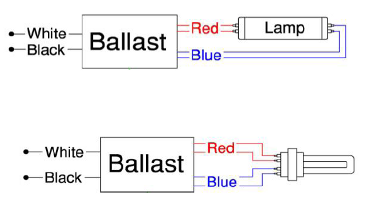
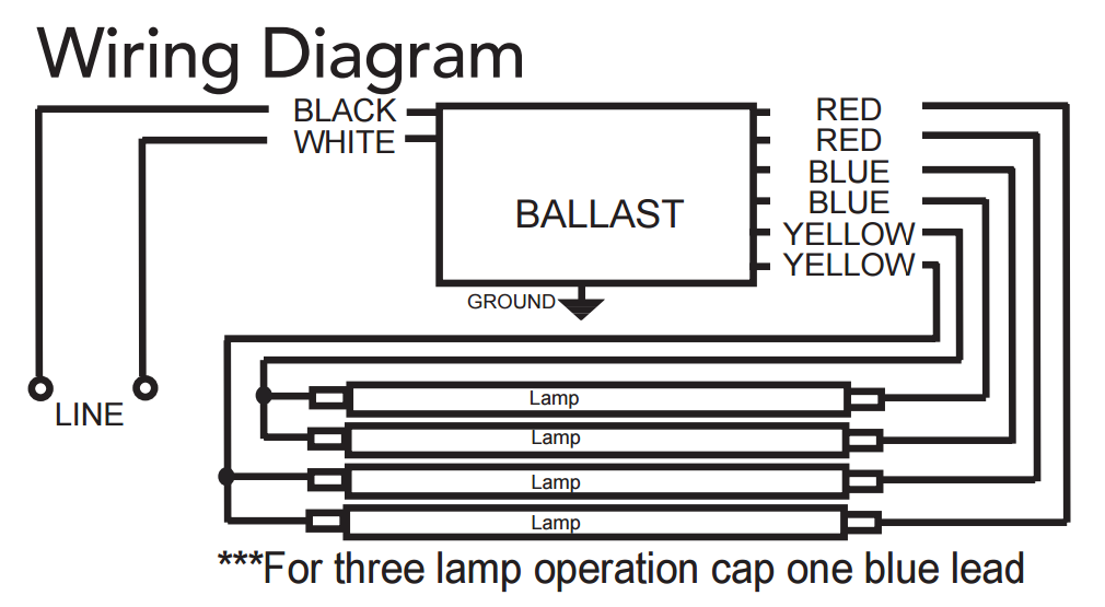
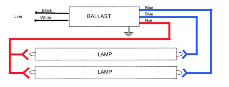
T8 ballast wiring diagram robertson. 2 lamp rapid start to. Example of wiring a t8 ballast. Each electronic ballast has a complete wiring diagram attached to the ballast which describes the specific wiring configuration from the ballast wire leads to the lamp sockets. Robertson ballast wiring diagram wiring diagram is a simplified pleasing pictorial representation of an electrical circuit it shows the components of the circuit as simplified shapes and the power and signal links along with the devices.
A wiring diagram is a streamlined standard pictorial representation of an electrical circuit. It actually is a lot simpler than then you think. Variety of fluorescent ballast wiring schematic. Wiring the electronic t8 ballast.
Pay close attention to the wiring diagram on the ballast as the new electronic t8 ballast are wired quite differently from the old magnetic t retrofit wiring diagrams. Youtube magnetic vs electronic balast wiring for t8 fluorescent. It reveals the elements of the circuit as streamlined shapes and the power and also signal links in between the devices. The emergency ballast wiring guide this document has been customized to contain a wide library of individual dia grams for various installation applications.
Robertson worldwide is the industry s leading manufacturer of uv drivers uv ballast magnetic ballast fluorescent ballast and hid lighting ballast. Led bulbs duration. Using the existing socket wires. Watch as total bulk lighting provides an overview of the fluorescent t8 ballast and what all those wires mean.
If a diagram cannot be found within this selection consult customer service. We provide customers with high quality and cutting edge electronic products. The diagrams are categorized primarily according to the number of lamps in the.

Rss240t12mv A Robertson T12 Electronic Fluorescent Ballast

Ge Ge 2 F32 Mv Ballast 37336 Long Lamp Lighting Bulb

Ogjtlmxvgmapjm

Psa239t5mv Ah Robertson T5 Electronic Fluorescent Ballast

Icn 2s54 T Advance Electronic Fluorescent Ballasts F54t5ho Ballasts
Bbsf7lhmzct1dm

What Are The Two Yellow Wires From A Ballast For Quora

Explore Ballast For Lamps Amazon Com

Xar Dboy8pr4om
F96t12 Electronic Ballast Wiring Diagram Wiring Diagram

Dbme8vlwmknsom

T12 Replacement Ballast Wiring Diagram Wiring Diagram
